Fader Controller
Hardware Project, 2025
Arduino based fader controller for sending continuous midi Control Change values over usb. This controller is supposed to be bare bones and hands on. Making a DIY device I can easily fit 60mm faders into the build. Many of similar, small footprint, devices feature only 20mm faders.
Table of Contents
Media
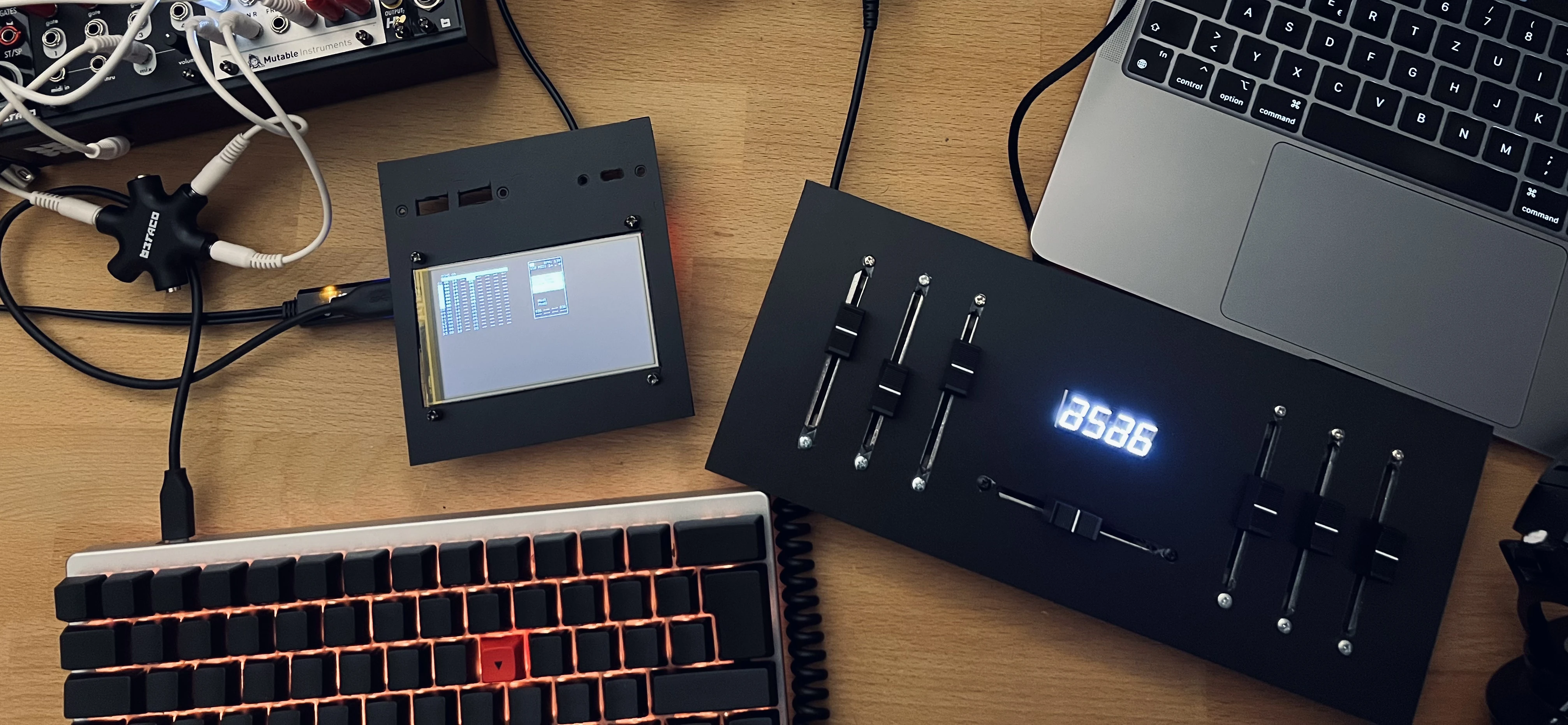
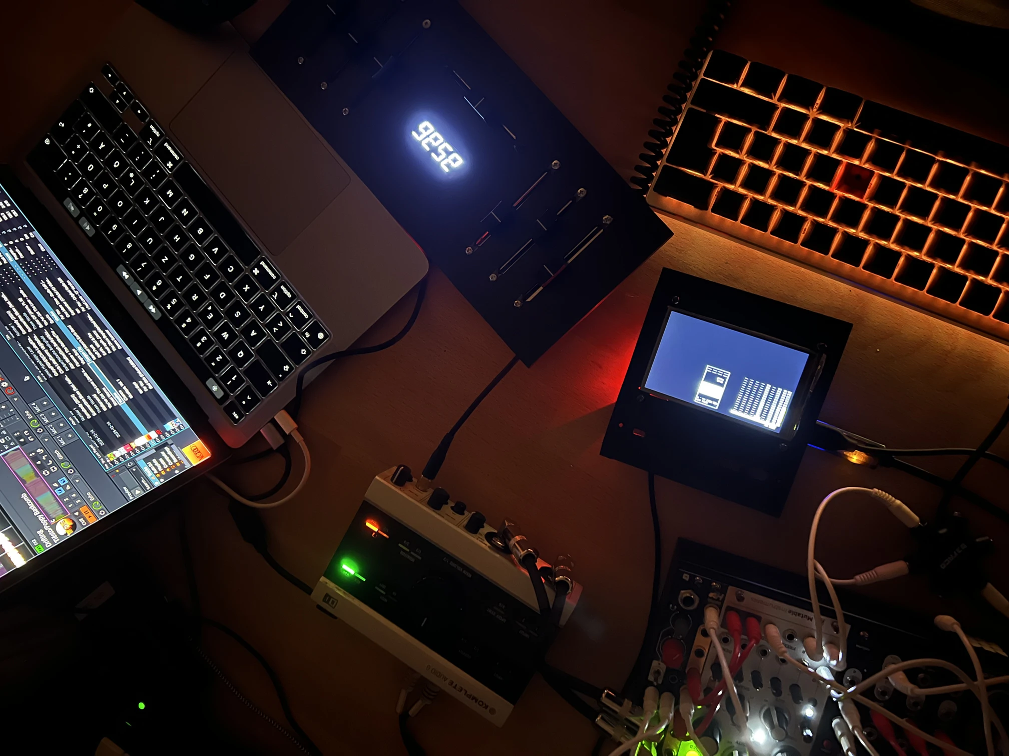 The battle mixer style layout is quickly setup to control two decks in the free and open source DJ software Mixxx.
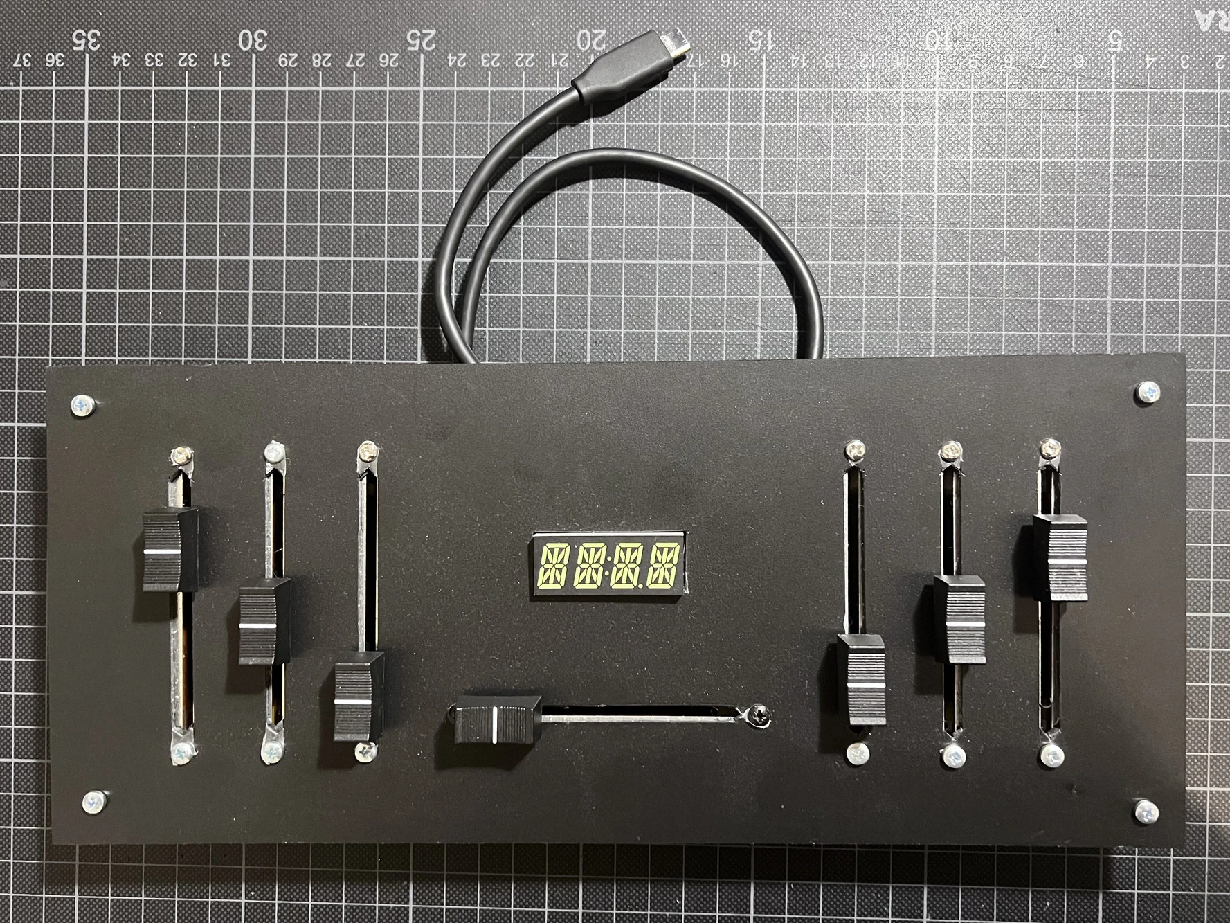
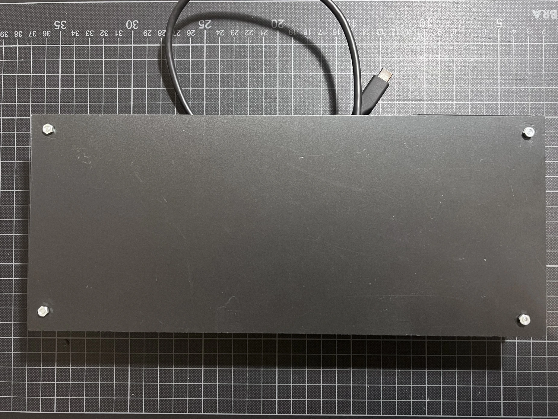 Front and back neatly hiding all the wiring.
FLASH WARNING | STROBES | FLASH WARNING | STROBES
The controller in usage at DENOISED, controlling the VJ parameters for A/B-switching and fine manipulations.
Part List / BOM
This guide/documentation is still work in progress.
| 1× | Arduino Pro Micro | USB library on github | |
| 1× | Alphanumeric Display | display library on github | |
| 8× | Linear Potentiometers, 10kΩ | ||
| 8× | Fader Caps | ||
| 1x | rigid foam board, 2mm |
Foam Board
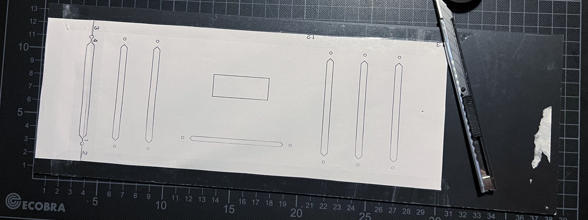 Download and print the pattern for the Foam board as PDF or as SVG. The pattern exceeds the A4 Paper size and thus needs to be stitched togehter as shown in the photo above.
Glue the stitched pattern to the foam board, securing it on all sides. When cutting the foam board take care to cut vertically through the board. The holes for the fader screws are close to the slits, make
Linear Potentiometer
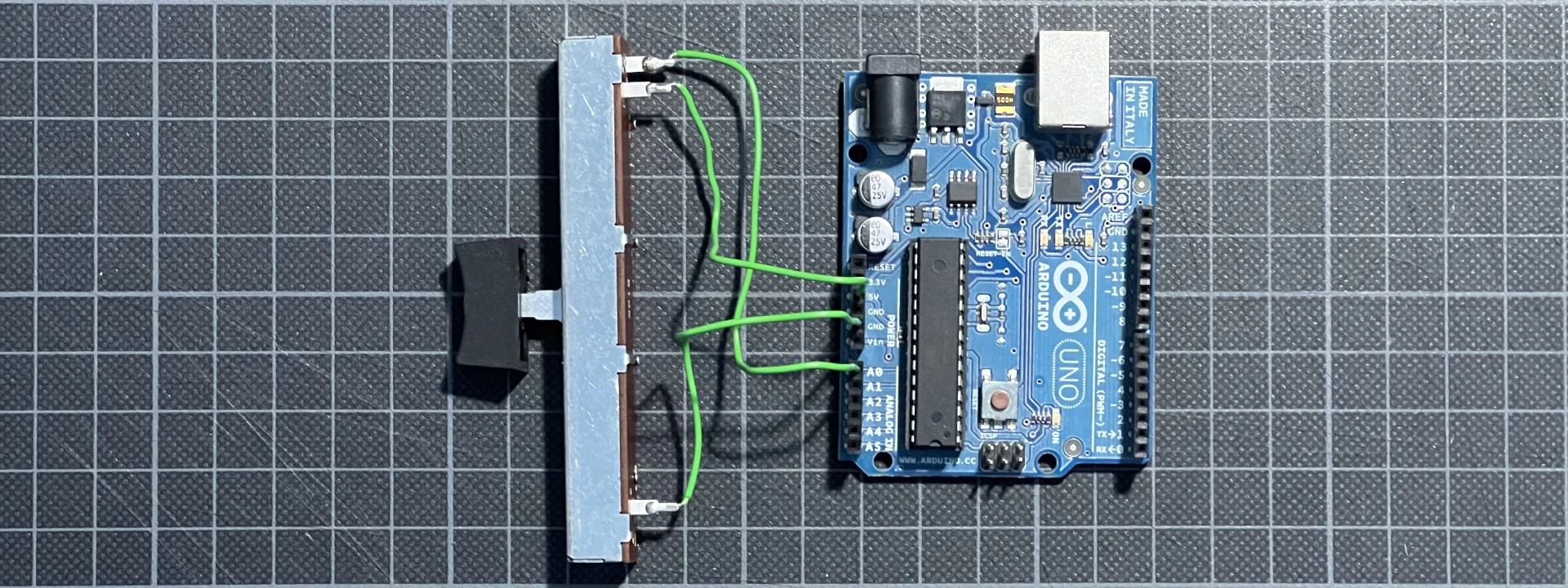 Make sure you know how to connect the pots correctly to your board. You should be able to measure the variable resistance with an Ohm meter. If you do not have such a device at home you can use a test setup like this. But make sure not to fry your board with a short circuit.
You can also build this with regular rotary potentiometers, which work by the same electrical principle. The setup descirbed does NOT work with endless encoders, which are digital and need a diffrent wiring and programming.
Wiring
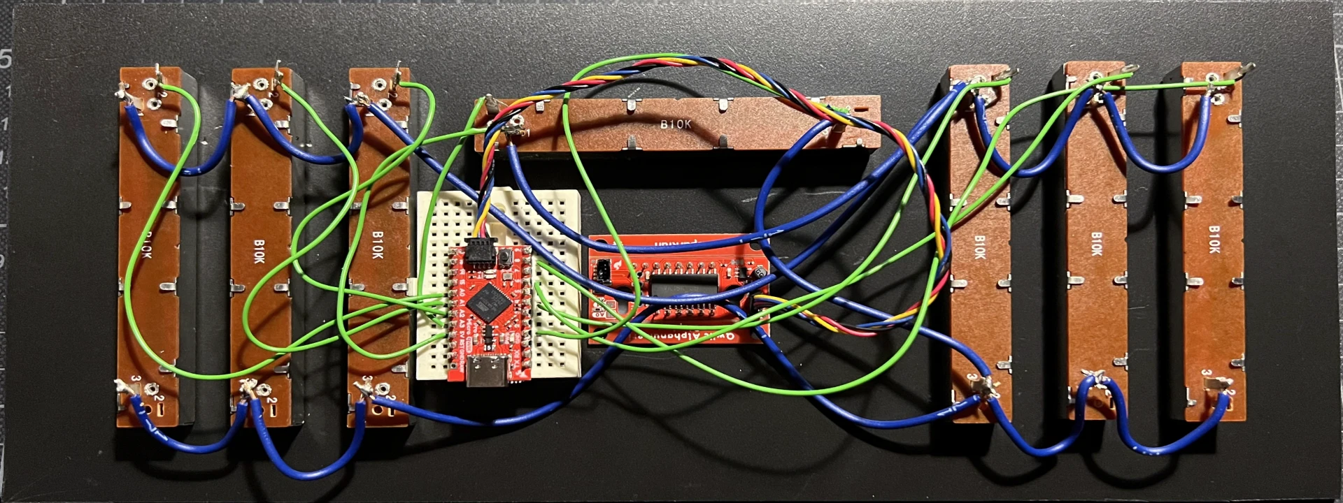 The wiring of this project is pretty straight forward, connect all grounds to the GND on the board, as well als all VCCs to +5V. Then only the outputs of the pot need to be soldered to their respective pins on the Arduino Pro Micro. I used pin headers and a breadboard for testing out the circuit. For a finished product you should solder the device and cables to a perf board, or solder the wire directly to the board.
The display used does connect via sparkfun qwiic and does only need the qwiic cable but no soldering.
Testing
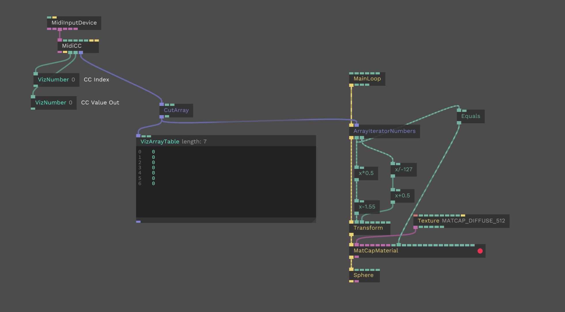
To test and debug the initial build a cables.gl patch mirrored the movement of the faders. Helping with polarities and making sure to minimize jitter and keep the assigend CCs in the right order.

Links
Repository on github: https://github.com/zuggamasta/usb-midi-fader
This uses BLOKAS/USBMIDI: https://github.com/BlokasLabs/USBMIDI